Recovered early-1980s project
Audio Simplex System Module
The recovered dualASSM001.wrl model combines one motherboard with two populated
daughter boards. “ASSM” was the project abbreviation for Audio Simplex System Module.
Original single-microphone TTL version
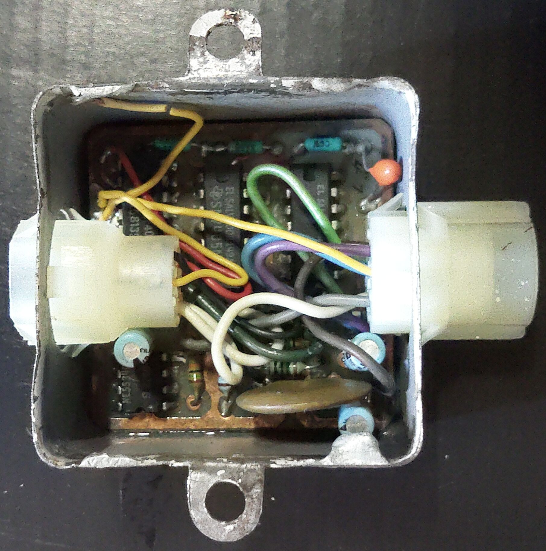
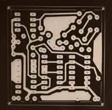
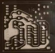
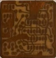
The first ASSM was a single-microphone version using TTL logic. One of those original units has now been found and photographed, and the original circuit board and photographic PCB artwork used in producing the boards also survive.
These photographs preserve an earlier stage of the project than the later two-station motherboard-and-daughter-board assembly shown in the interactive VRML model below.
This browser could not start the VRML viewer.
pcb-003.wrl alias so its two original daughter-board links resolve correctly.
Project history
These modules were installed beneath the service counters in Burger King restaurants. Each daughter board served a counter station equipped with a microphone, a talk switch, and red/green status indication. The motherboard joined the station circuits to the shared audio and control wiring.
The center motherboard connector carried the daisy-chain cable from one module to the next and eventually back to an amplifier in the kitchen. A separate kitchen board accepted that cable and also served as the system power supply.
How the simplex system worked
- With the audio line available, the microphone-stand indicator was green.
- Pressing a station's talk switch changed the state of the shared control wire.
- An electronically controlled analog switch connected that station's microphone audio to the common line.
- The same control state locked out the other microphones and changed their indicators to red.
- Releasing the talk switch returned the shared line to its available state.
It was therefore a simplex system: several stations shared the wiring, but only one microphone could transmit at a time.
Two documented design generations
The first version used one circuit per unit, TTL logic, and an NE5534 operational amplifier. It used an open-collector control line so a station could assert the shared busy condition without logic outputs fighting one another.
This second version changed the control logic to CMOS and used a transistor to provide the open-collector function. The audio path was selected by a semiconductor analog switch—an electrically controlled switch that acted somewhat like a solid-state relay for the audio.
Reconstructing the first ASSM logic — one step at a time
The surviving first-generation board gives us four important ICs to work from: the NE5534 audio amplifier, a 7405N open-collector inverter, a 7413 NAND-gate package, and a 4016 quad bilateral switch. We know one 4016 section switched the microphone audio. The pushbutton Talk switch and the shared control line were the two outside conditions the logic had to watch.
Step 1 — Give each condition a one-letter name
The 4016 microphone switch can then follow Q: when Q = 1 the microphone path is connected; when Q = 0 it is disconnected.
Throughout this lesson we will use the older, compact notation ~A to mean NOT A.
Step 2 — Start with the obvious idea
At first it seems that the microphone should turn on only when the Talk button is pressed and the line is free:
That sounds right, but it contains a trap. As soon as this station takes the line, its open-collector output makes the shared line busy. In our notation that changes F from 1 to 0. The simple equation would therefore turn the microphone straight back off.
Step 3 — Add the “already active” condition
While the Talk button remains pressed, this station should stay active when either:
- the line was free, or
- this station already owned the line.
That gives us the working Boolean expression:
Read it in plain English as: “Talk must be pressed, and the line must either be free or already belong to me.”
| T | F | Q | Qnext | What happens |
|---|---|---|---|---|
| 0 | X | X | 0 | Talk released — this station lets go. |
| 1 | 1 | 0 | 1 | Line free — this station takes it. |
| 1 | 0 | 0 | 0 | Another station has it — this station is locked out. |
| 1 | 0 | 1 | 1 | This station already has it — keep talking. |
The X means “don't care.” If the Talk button is not pressed, the station must be off regardless of the other two conditions.
Step 4 — The straightforward gate drawing would contain an OR
Break the equation into two smaller jobs. First make an intermediate signal S:
Then combine that result with the Talk switch:
If we built that expression literally, we would reach for an OR gate followed by an AND gate. But the surviving first-generation unit does not contain a separate OR-gate IC. This is where De Morgan's theorem earns its keep.
Step 5 — Use De Morgan to make the OR from NAND and NOT
One of De Morgan's identities is:
So our intermediate OR signal can be rewritten as:
Now the hardware match becomes very attractive: two 7405 inverter sections can produce ~F and ~Q, and a 7413 NAND section can perform the inversion of their AND. The result is exactly F + Q — without a separate OR chip.
Because the 7413 NAND gate has more inputs than this two-variable expression needs, the unused inputs can simply be held at logic HIGH so they do not change the NAND result.
Step 6 — The final AND can also be made from NAND plus an inverter
We still need:
A NAND gate gives the inverted answer first:
One more 7405 inverter restores the desired polarity:
In other words, the 7413 NAND gates plus spare 7405 inverters can reproduce the AND/OR/NOT logic without needing a separate OR-gate package. That is exactly the kind of parts-count reduction designers commonly looked for when board space and IC count mattered.
Step 7 — Add the red and green indicators
Our present recollection is that green meant the shared line was available, while red meant that another microphone was already using it. If that memory is correct, a useful first model is:
The second equation is important: the red lamp means someone else owns the line, not merely that the shared line is busy. If this station itself owns the line, Q = 1 and the red indication is suppressed.
A later two-color bilateral LED would not change these logical states; it would only change how the two indicator outputs were wired to the lamp.
Step 8 — Put the whole idea into one sentence
Press Talk to seize a free line; once this station has seized it, keep it until Talk is released; if another station already owns it, stay locked out.
Once the required behavior has been expressed this way, we no longer need to depend on one particular old board revision to determine the functional logic. The Boolean expression itself is enough to draw a gate-level schematic.
Step 9 — Turn the Boolean expression into a functional schematic
We can now assign each part of the expression to a logic function. This is a functional reconstruction: it tells us what must connect to what logically, even though resistor values, exact IC pin numbers, power-supply details, and the precise LED driver wiring still belong to the later component-level schematic.
As we build that drawing in the next steps, schematic illustrations will use the shared light-blue / dark-red LearnTronics schematic style so they remain visually distinct from the beige equation panels and the pink truth tables.
| Stage | Function | Signal produced |
|---|---|---|
| 7405 inverter | Invert the shared Free signal | ~F |
| 7405 inverter | Invert this station's active state | ~Q |
| 7413 NAND A | Use De Morgan to make the OR term | S = ~(~F · ~Q) = F + Q |
| 7413 NAND B | Combine Talk with the OR term | N = ~(T · S) |
| 7405 inverter | Restore the desired active-high state | Q = ~N = T(F + Q) |
| 4016 switch | Use Q as the control for the microphone audio path | Microphone connected when Q = 1 |
| 7405 open-collector inverter | When Q is active, pull the shared control line to its Busy state | The other stations see F = 0 |
In compact form, the logic path is therefore:
The shared control line needs a pull-up because a 7405 output can pull the line LOW but does not actively drive it HIGH. The exact pull-up value is an electrical-design choice, not something Boolean algebra can tell us.
At this point we have enough information to draw a clean schematic from first principles, rather than trying to reverse-engineer one particular photograph.
Present status of the reconstruction
The VRML files preserve the mechanical arrangement and much of the component placement, but the daughter-board traces were never completely finished in the surviving model. The original schematic is not currently available. We can reconstruct a functional logic schematic from the required behavior, but a historically exact component-level schematic should still be labeled as a reconstruction unless an original drawing is recovered.